Open an AI server and the expensive processors attract attention first. Step back and another system becomes visible: network interfaces, switches, cables, optical modules, patch panels, and the routes that connect one group of machines to another. Those connections determine how effectively the processors can work together.
An accelerator can complete its arithmetic quickly and still wait for a result from somewhere else. A link can advertise an impressive speed and still share a congested path. A laser can be highly efficient while the complete connection consumes substantial power in its electronics. Understanding the optical data center means following these dependencies across several physical scales.
My central view is that the optical opportunity comes from making a larger system useful. The important questions are where data must travel, how often it must move, what electrical signals can tolerate, and how the equipment will be operated. The answer changes with the workload and the location of the connection. There is no single optical architecture that automatically wins everywhere.
Source and scope. This original primer was prompted by Leo Cui’s “Why AI Needs Lasers | Lumentum Explained”, publicly dated August 6, 2026. Research covered the complete 14:16 transcript and selected visual demonstrations, followed by primary technical and company sources. The discussion below substantially expands the optics and facility-design topics. It uses original explanations and figures, with Lumentum as one industry case study. Company observations are dated to September 16, 2026. Calculations marked illustrative are teaching examples, not measured product performance or engineering specifications.
1. Begin with the work that must cross the network#
Suppose four processors are helping train a model. Each works on part of a calculation, but the next step requires a combined result. Completing one local task is not enough: the machines must exchange information and agree on what comes next. The time spent communicating becomes part of the job's completion time.
The precise pattern matters. In an all-reduce, participants combine values through an operation such as addition, and every participant receives the combined result. An all-gather distributes each participant's contribution to the others. An all-to-all exchanges different portions of data between participants. These patterns create different demands on paths, scheduling, and available bandwidth. They are described in NVIDIA's collective-communication documentation.
This is why adding faster processors does not guarantee a proportional improvement in a distributed job. Imagine an illustrative step containing 80 milliseconds of computation and 20 milliseconds of communication that cannot overlap. Halving the computation produces a 60-millisecond step, not a 50-millisecond step. The improvement is 100 divided by 60, or about 1.67 times. This arithmetic is a teaching model: real systems overlap work, distribute it unevenly, and encounter multiple bottlenecks.
Inference introduces its own patterns. Some models fit on one accelerator; others span several devices or servers. A service may move cached state, route tokens to experts, or separate different stages of request processing. It is inaccurate to say that every answer from every chatbot requires thousands of GPUs to communicate. The deployment and model architecture determine the requirement. NVIDIA's multi-device inference explanation provides a concrete example of inference that does use distributed communication.
Before asking whether a data center needs more optics, ask what crosses the boundary. Is the traffic a large sustained transfer, many small messages, a burst synchronized across machines, or a response that cannot wait behind other work? This question connects physical infrastructure to useful performance.
2. Separate three scales of connection#
The first scale is scale-up: tightly connecting processors into a larger compute domain. The second is scale-out: connecting groups of machines so they can cooperate across a larger cluster. The third is communication between facilities or locations, sometimes called scale-across. These names describe architectural roles; they do not impose a universal distance or cable material.
A scale-up domain can extend beyond one rack. A scale-out link might be short enough for copper or long enough to need fiber. A connection between buildings has different route, protection, and optical-budget requirements from a connection between neighboring servers. Drawing a fixed boundary at the rack and labeling everything inside copper and everything outside fiber would hide important design choices.
It also helps to distinguish a protocol from a physical medium. Ethernet and InfiniBand specify communication systems. Copper and optical fiber carry signals. Ethernet is not synonymous with optics, and an optical cable is not a complete description of the network's behavior. Link speed, topology, congestion handling, host interfaces, and software all affect the result.
Google's May 2026 network-design discussion separates tightly coupled compute, a dedicated accelerator scale-out network, and networks serving frontend compute and storage. It is a useful reminder that a large operator can deploy several fabrics for different jobs. Its named architectures should not be treated as the blueprint for every facility. Google Cloud's AI-era network architecture.
For the rest of this primer, keep two maps in mind. The logical map shows which processors, servers, and switches exchange data. The physical map shows where equipment sits and how cables reach it. A design is complete only when the two maps agree.
3. Follow one direction of an optical link#
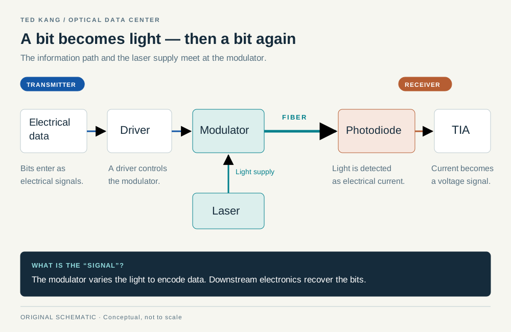
An optical link begins with electrical information and ends with electrical information. Between those endpoints, light carries the encoded signal. Separating the stages makes the equipment much easier to understand.
The transmitter needs a source of light and a way to put information onto it. A laser supplies optical energy. A modulator changes a property of the light according to the data. Photonic waveguides and couplers guide the light through a chip and into a fiber. The fiber carries it to the other end. These functions may be integrated closely or distributed across several components. Cisco's silicon-photonics engineering overview.
At the receiver, a photodiode converts received optical energy into an electrical current. A transimpedance amplifier, or TIA, turns that small current into a usable voltage. Other electronics recover the information from the signal. The division of work depends on the interface, but the photodiode and amplifier have distinct jobs. Cisco's receiver-component explanation.
A transceiver contains transmitting and receiving functions. A common pluggable version can be inserted into the faceplate of a switch or network interface. The metal module is a small system containing optical components, electronics, packaging, and a fiber connection. A laser chip is one component within the broader system, not another name for the complete module.
This distinction matters commercially as well as technically. Selling the laser, assembling the module, designing the switch, and operating the cluster are different roles. One company can occupy more than one role, but revenue from those roles should not be counted repeatedly as separate end-market demand.
4. What an EML does, and what silicon photonics changes#
An electro-absorption modulated laser, or EML, combines a laser section with a modulator section. In Lumentum's description, a distributed-feedback laser provides continuous light and an adjacent electro-absorption modulator applies the high-speed data signal. The integrated device uses indium-phosphide technology. The two sections perform different functions even though they are manufactured together. Lumentum's EML architecture.
It is useful to move beyond the familiar picture of a light blinking on and off. Modulation can produce distinguishable levels or change other properties of the optical signal. The laser does not necessarily have to turn fully off for each encoded zero. The exact representation follows the chosen signaling scheme.
Silicon photonics uses silicon-based manufacturing and optical structures to integrate functions such as guiding and modulating light. Silicon is valuable for these functions but is an inefficient light emitter in ordinary implementations. A silicon-photonic design can therefore use a light source made with another semiconductor material. Intel and UC Santa Barbara demonstrated an InP/silicon hybrid laser as early as 2006, combining the emitting material with silicon waveguides. Intel's original hybrid-laser announcement.
The phrase “silicon photonics replaces lasers” gets the relationship wrong. The question is which laser, how it couples into the optical circuit, and where it is located. A separate continuous-wave laser can feed modulators on a photonic chip. Other approaches integrate or bond the emitting material more closely. Intel's product description illustrates an integrated laser-array approach, while other system designs use external laser sources. Intel silicon photonics.
For a supplier, this can change the mix of products customers need. Demand might move between integrated EML devices, continuous-wave sources, photonic engines, and packaged modules. A change in architecture can create an opportunity for one product while challenging another. “More optics” is too broad a category to resolve those effects.
5. Decode the numbers on the front of the module#
An 800-gigabit-per-second interface has a nominal rate of 800 billion bits per second. Dividing by eight gives 100 billion bytes per second, or 100 decimal GB/s, before making the relevant allowances for overhead and application behavior. It is not 800 GB/s. A product's aggregate bandwidth may also sum several ports or both directions, so the denominator deserves attention.
The rate can be assembled from multiple lanes. Eight nominal 100G lanes and four nominal 200G lanes can both sum to an 800G interface. That arithmetic does not establish identical devices, cables, reach, cost, or power. Nor does doubling the total interface rate necessarily double the number of lasers: the design may increase the rate per lane, change the number of lanes, or change how wavelengths are supplied.
Baud measures symbols per second. Bit rate measures bits per second. PAM4 uses four distinguishable amplitude levels, which represent two bits per symbol. Four levels do not represent four bits. The physical signaling rate also includes coding overhead, so a marketing rate should not be converted into an exact baud rate without the interface specification. Keysight's bits-versus-symbols guide.
A simple analogy is a messenger who can carry one of four labeled cards. Each card can represent a pair of bits: 00, 01, 10, or 11. The receiver must distinguish the cards reliably. As the differences between signal levels become smaller relative to noise and distortion, reliable identification becomes harder. That challenge explains why increasing rate requires more than simply running the same hardware faster.
Forward error correction, or FEC, adds structured redundancy so a receiver can repair a bounded amount of corruption without retransmitting the entire message. It consumes overhead and requires processing. It cannot repair an arbitrarily poor connection. Cisco documents interface-specific examples in which FEC resides in the host and others in which it resides inside the module. Cisco's FEC explanation.
A digital signal processor, or DSP, can condition, recover, or retime signals. DSP and FEC are related parts of link engineering, but they are not interchangeable names. Removing a particular module DSP does not imply that the complete link has no digital processing or error correction.
6. Fiber, wavelengths, and lanes are different things#
The word mode describes how light propagates spatially through the fiber. Multimode fiber supports multiple spatial modes. Single-mode fiber is designed for one spatial mode in its intended operating range. Single-mode does not mean one wavelength, one bitstream, or one strand per connection. Corning's optical-fiber basics.
There are several ways to carry more information. A design can send a faster signal through a lane. It can use more fibers in parallel. It can also place several wavelength channels on the same fiber through wavelength-division multiplexing, or WDM. The receiving end separates the wavelength channels again. These approaches can be combined; they solve different packaging and capacity problems.
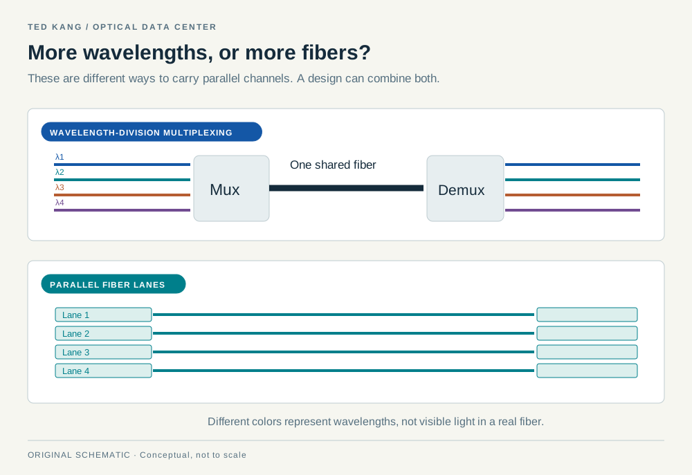
Concrete specifications help. Cisco's 400G DR4 example uses four fiber pairs and specifies 500 meters of reach. Its 400G FR4 example uses four wavelengths over a duplex fiber connection and specifies 2 kilometers. These are examples of named interfaces, not universal limits for all optical links. Their cable requirements differ even though each carries a nominal 400G service. Cisco 400G module specifications.
The same caution applies at 800G. Cisco lists an 800G DR8 product with eight fiber pairs and a 500-meter specification, alongside a dual-400G FR4 module using two duplex connections and a 2-kilometer specification. The latter is not evidence that every device marketed as “800G FR4” has the same optical layout. Read the particular interface and module definition. Cisco OSFP 800G specifications.
For facility design, the consequences include cable volume, connector type, patch-panel capacity, route availability, and how a connection can be broken out into smaller interfaces. A faster module can simplify one part of the network while making installation and inventory more demanding elsewhere.
7. Distance creates a budget, not a magic cutoff#
Copper remains useful when the required rate, reach, power, and mechanical constraints fit. At higher frequencies and longer electrical paths, attenuation, reflections, and interference become more difficult to manage. Equalization and retiming can help, but they add design requirements and may consume power. The point at which optics becomes attractive depends on the complete link.
Optical fiber has its own impairments. Light is lost through the fiber and at connectors, couplings, and splices. Dispersion can spread a signal in time. The receiver must distinguish the information despite those effects and noise. A link that receives enough optical power can still have an unacceptable signal quality. Conversely, a nominal distance rating assumes the specified channel conditions, not any arbitrary collection of connectors along that distance.
A simplified power budget shows the accounting. Suppose an illustrative transmitter launches 0 dBm and the assumed receiver threshold is −6 dBm. The raw allowance is 6 dB. If modeled fiber loss is 0.4 dB, connectors contribute 1.5 dB, other passive elements consume 1.0 dB, and the designer reserves 2.0 dB, the arithmetic leaves 1.1 dB. Those invented values teach subtraction in decibels; they do not establish a compliant link, a bit-error rate, or an optical modulation amplitude budget.
Operational designs need the actual transmitter and receiver specifications, required measurement definitions, temperature range, aging assumptions, and all relevant penalties. Corning's design tools separately address optical link loss, tray capacity, conduit fill, and related planning needs. Their separation reinforces that optical and mechanical feasibility are distinct checks. Corning system-design calculators.
Latency is another budget. It includes propagation, serialization, electronics, switching, and waiting in queues. A faster port can shorten the time required to send a given amount of data; it does not eliminate the travel time along the route. Light in ordinary fiber also travels more slowly than light in vacuum. Optical connectivity is valuable for capacity, reach, and system efficiency, not because every optical connection has zero or negligible delay.
For an illustrative 1,500-byte message, serialization alone is 12,000 bits divided by the link rate. That is 30 nanoseconds at 400 Gb/s and 15 nanoseconds at 800 Gb/s, excluding Ethernet overhead and all other delays. A queue can easily dominate such a narrow arithmetic improvement. This is why a network design must consider traffic behavior alongside nominal speed.
8. Turn port speeds into a network#
A leaf-and-spine network connects servers to leaf switches and connects those leaves through spine switches. In a simple design, each leaf reaches each spine. Traffic moving between leaves can take more than one path, while the number and capacity of uplinks determine how much traffic can leave a leaf at once.
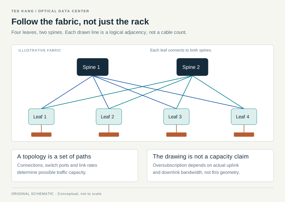
Consider a separate worked example with four leaf switches. Each leaf connects sixteen 400G server ports, giving it 6.4 Tb/s of server-facing nominal bandwidth. Suppose that leaf also has eight 800G uplinks, four to each of two spines. Its uplinks also sum to 6.4 Tb/s. The capacity ratio at the leaf is 1:1. This balanced count still requires suitable switch capacity, path selection, and workload behavior before the network can deliver the intended performance.
Across all four leaves, there are 64 server-facing links and 32 leaf-to-spine links. If every one uses a conventional optical module at both ends, the corresponding count is 192 endpoint modules. That is a deliberately bounded example: it excludes management, storage, intersite connections, extra resilience, and breakouts. Copper links or integrated optics would change the bill of materials.
Now reduce each leaf to four 800G uplinks. Server-facing capacity remains 6.4 Tb/s, but uplink capacity falls to 3.2 Tb/s. The resulting 2:1 oversubscription can be reasonable for some traffic patterns and restrictive for others. It is not a promise that each server always receives half its advertised speed. The outcome depends on which servers transmit simultaneously and where their traffic needs to go.
Radix refers to the number of ports or connections a switching element supports at a stated rate. Higher radix can allow a topology with fewer stages, but the equipment still needs practical cabling, thermal design, and failure handling. Bisection bandwidth measures capacity across a cut dividing the network into two equal-sized groups of endpoints, considering the least-capable such cut. It is a system property, not the sum of every port label printed on every switch. Cornell's network concepts and terminology.
The useful commercial lesson is that optical demand cannot be inferred from accelerator count alone. Topology, port rate, the number of network planes, cable reach, and redundancy determine how many optical endpoints are installed. Two clusters with similar processor counts can require different optical bills of materials.
9. Move the conversion point: pluggable optics and CPO#
In a conventional pluggable arrangement, a high-speed electrical signal travels from a switch chip across a circuit board to a module at the faceplate. The module converts the signal into light. Making the optical conversion happen closer to the chip shortens the electrical route that the high-speed signal must survive.
Co-packaged optics, or CPO, places optical engines close to the main chip within a package assembly. The motivation is connected to electrical reach, signal integrity, density, and power. The switch can still examine and forward packets electronically. CPO does not mean that the switch's logical decision-making has become an optical computation. Broadcom's CPO overview.
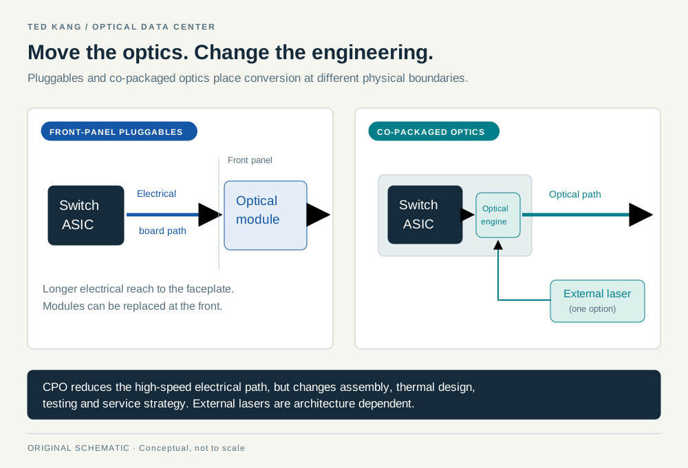
NVIDIA's photonics design description includes optical engines near the switching ASIC and externally accessible laser sources. Keeping the laser accessible addresses one service consideration; it does not make the integrated engine or every fiber attachment equally easy to replace. A technician needs to know which part failed and what must be removed to restore service. NVIDIA's silicon-photonics switching explanation.
This creates a useful tradeoff. Integration can eliminate difficult connections and reduce some component requirements, but it also changes assembly, testing, thermal interaction, and repair. The best design is evaluated as an operating system of equipment, including maintenance and qualification. A laboratory power comparison alone cannot settle that decision.
10. LPO and LRO change processing, not just packaging#
Linear pluggable optics, or LPO, removes the conventional module DSP and depends more heavily on the host and the quality of the complete channel. The resulting module can have a different power and latency profile, but the host, module, connectors, and fiber must work together with sufficient margin. LPO MSA specification, sections 4–5.
Linear receive optics, often called LRO, retains transmit-side retiming while using a linear receive path. OIF uses the more explicit phrase retimed transmit, linear receive, or RTLR. These are choices about where signal conditioning occurs. CPO, by contrast, describes physical integration. They are separate dimensions of design, not simply successive generations on a single speed ladder. OIF's CEI-448G framework and terminology.
| Term | What primarily changes | The question it leaves open |
|---|---|---|
| Retimed pluggable | A replaceable module includes signal-processing functions | How demanding is the host-to-module channel? |
| LPO | More of the link depends on host-side processing | Is the full channel qualified with enough margin? |
| LRO / RTLR | Transmit and receive use different processing arrangements | Which tradeoff fits the channel? |
| CPO | Optical engines move close to the main chip | How are heat, testing, and repair managed? |
| Optical I/O | Optical connectivity reaches a compute-package boundary | What protocol and integration requirements apply? |
The LPO MSA's specification is a concrete check against the claim that LPO has no error correction. It specifies FEC as part of the connection. Its publication is also an MSA specification, which should not be casually relabeled as an IEEE standard. LPO MSA specification.
For a buyer, the practical issue is interoperability. A module that works in one carefully qualified host and cable arrangement is not automatically interchangeable with every host sharing the same nominal rate. Qualification includes the electrical path and the operating environment. The LPO MSA's specification release describes its work on interoperable implementations. Removing a component changes where responsibility sits; it does not remove the need to verify the end-to-end result.
11. Optical I/O and coherent links solve different distance problems#
Optical I/O brings the conversion boundary toward the compute package itself. It is one proposed way to provide more communication bandwidth without requiring every high-speed signal to travel a long electrical route. Its relationship to a CPU or accelerator is different from the relationship between a faceplate transceiver and a rack switch.
Intel's June 2024 optical-I/O demonstration provides a useful, bounded example. It described a CPU-connected prototype with 64 channels of 32 Gb/s in each direction, about 2 Tb/s per direction or about 4 Tb/s when both directions are summed. The demonstration was explicitly a prototype. It was not proof that every server could purchase and deploy that configuration, and its energy comparison should not be generalized to a complete facility. Intel's optical-I/O demonstration.
At the other end of the distance spectrum, coherent optics uses a receiver architecture that can recover information encoded through properties including phase, amplitude, and polarization. This differs from the simple intensity-modulated, direct-detection link used as the introductory example. Coherent processing can support demanding transport applications, but it brings its own optics, electronics, and design tradeoffs. Cisco's coherent-modulation explanation.
OIF's 400ZR agreement illustrates why reach claims need context. It specifies particular amplified point-to-point applications and a separate unamplified loss-limited application. A shorthand distance attached to “400ZR” does not mean any fiber route of that length will work without the specified optical system. OIF 400ZR implementation agreement.
These labels describe different properties: optical I/O identifies an integration boundary, while coherent identifies a signaling and receiver approach. The examples bracket a broad field. A chip-package connection, a row-to-row connection, and a metro link can all use photonics while requiring very different products. An investor or reader who treats them as one undifferentiated technology will miss both the engineering and the business boundaries.
12. Optical circuit switching changes the paths#
An optical circuit switch, or OCS, establishes a light path between ports. A MEMS implementation can steer that light using very small movable mirrors. It acts like configurable optical wiring: the circuit is established, then signals travel through it. It does not inspect each packet's destination and buffer competing packets as an electronic packet switch does. Lumentum's R300 OCS description.
An OCS can avoid an optical-to-electrical-to-optical conversion at a particular intermediate point. That does not eliminate conversions at the endpoints or every electronic switch elsewhere in the system. It also introduces a control problem: someone must decide which circuits should exist and coordinate changes with the workload and the network.
Google's Jupiter work is an example of optical circuits combined with software-controlled topology. Its published research describes changing a particular interconnection architecture and supporting upgrades over time. Performance and cost results from that combined design belong to that design; they are not generic percentages that can be applied to every OCS installation. Google Research, “Jupiter Evolving”.
A separate example appears in Google's Ironwood description. OCS connects groups of accelerators, and a fabric manager can work around an unhealthy group or link using available healthy resources. The published design includes 64-chip cubes and a 9,216-chip superpod. That is evidence for a specific engineered system, not a requirement that all AI clusters use the same grouping. Google's Ironwood engineering explanation.
The reader should distinguish three actions in any animation: a controller choosing a circuit, optical hardware establishing the path, and data subsequently using it. A mirror should not appear to make a new routing decision for every illustrated packet. Reconfiguration time and the effect on traffic must remain explicit rather than disappearing behind a smooth transition.
13. The optical network must fit a real building#
Networking diagrams are clean. Buildings contain cable trays, doors, hot equipment, service aisles, support structures, and technicians who have to identify the right connector. The physical arrangement can make a theoretically attractive network expensive to install or difficult to operate.
Start with the routes. The distance between two racks on a floor plan is not necessarily the cable length between their ports. The cable may rise into a tray, pass through a distribution point, follow an approved path, and include service slack. Connector and patch-panel choices also affect the optical path. A cable schedule must describe the route that will actually be built.
Fiber handling matters. Connector contamination can reduce optical performance, and access for inspection, cleaning, and replacement is part of the design. Corning's connector guidance addresses the relationship between end-face condition and optical performance. Corning connector-cleaning guidance. Bend limits are product-specific and may differ during installation and normal operation; a single radius should not be printed as a universal rule for every cable.
Then consider heat. Optical modules consume electrical power and must operate within their allowed environment. A faceplate crowded with modules creates a different service and thermal problem from optical engines integrated beside a hot ASIC. Moving a function changes where its heat must be removed; it does not make that heat disappear.
Finally, trace failure boundaries. Two logical paths sharing one physical tray can be damaged together. Two fabrics can depend on the same power, cooling, or control system. An integrated optical engine may have a different repair procedure from an accessible pluggable module. Redundancy in a diagram is useful only when the relevant dependencies and recovery procedures have also been considered.
The most useful review questions are concrete: Which part can fail? How will the operator identify it? What has to be disconnected? How much capacity remains during repair? Which spare restores service? Those answers connect optical architecture to availability without inventing a universal failure rate.
14. Count watts across a clearly defined boundary#
Power claims are easy to misread because they often describe different parts of the system. A laser's electrical input, an optical engine's consumption, one transceiver's power, a complete switch's power, and a facility's total draw are different quantities. Compare like with like before drawing a conclusion.
Consider an illustrative network with 10,000 conventional optical links. If each has one 12-watt module at each end, the module total is:
10,000 links × 2 modules per link × 12 watts = 240,000 watts, or 240 kW.
At an assumed 8 watts per module, the same endpoint count would use 160 kW. The difference is 80 kW, or one-third of the initial module-only total. If both cases operated at those assumed powers continuously for 8,760 hours, the difference would be 700,800 kWh, or 700.8 MWh per year. At an illustrative electricity price of $0.10/kWh, that is $70,080 of direct electrical energy. No hardware price, cooling saving, or facility efficiency multiplier is included.
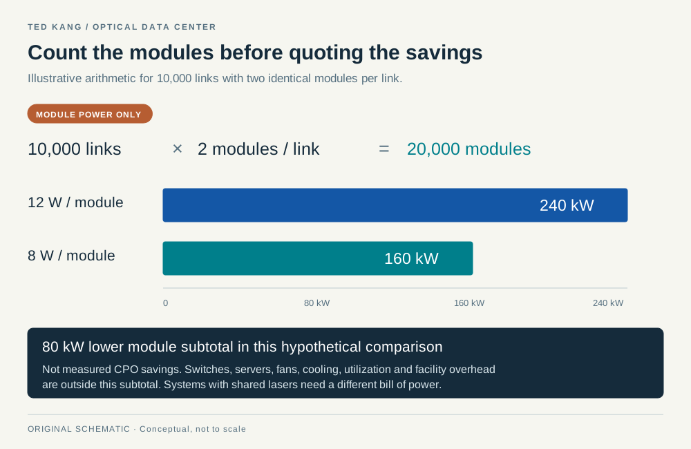
The boundary becomes more important when architectures change. A CPO system may share laser sources and integrate functions that were previously counted as separate modules. Multiplying an old pluggable-module count by a new engine power can compare unlike systems. The calculation needs a fresh inventory of both endpoints, shared supplies, host interfaces, and any retained retimers.
Energy per bit is another useful metric with a denominator. One watt divided by one terabit per second is one picojoule per bit. If the measured equipment carries less useful traffic while drawing similar power, energy per delivered useful bit increases. A number based on peak nominal bandwidth therefore answers a different question from a number based on actual application traffic.
Efficiency and total demand can also move in opposite directions. A hypothetical change from 10 to 6 pJ/bit is a 40% reduction in energy per bit. If deployed bit rate doubles, the corresponding power at those stated operating points rises by 20%, because 2 × 6 is larger than 10. Better optics can make a larger system feasible while the larger system still consumes more power.
15. Design around the workload, then choose the link#
Imagine a fictional operator, Harbor Compute, choosing connections for three parts of an expansion. The exercise is not a recommendation for a named product. It shows why the same purchasing rule should not be applied to every connection.
Within a compact compute domain, Harbor first evaluates its supported interfaces, required rates, and actual cable distances. If a qualified copper solution meets the requirements with acceptable power and handling, optical conversion is not automatically an improvement. If the domain grows or the electrical path becomes difficult, a different integration boundary may become attractive. The choice must fit the accelerator platform and its supported topology.
Between groups across a data hall, Harbor examines fiber routes, optical reach, breakout requirements, and serviceability. It compares complete endpoint configurations rather than laser efficiency alone. A faceplate module with a clear replacement procedure may have operational value even when a more integrated design promises lower power. A qualified integrated design may offer advantages where density and electrical reach dominate.
Between buildings, Harbor measures the actual route and optical budget and checks whether the connection belongs to the same tightly coupled job or supports a looser transfer. Distance and failure protection now matter in different ways. Sending a checkpoint to another site is not the same latency problem as placing every time-sensitive collective operation across that route.

Harbor's design review should leave a small set of explicit records: a traffic model, logical topology, physical cable schedule, qualified component combinations, power boundary, and failure-recovery plan. A change to one can affect the others. Moving a rack may alter a cable route; changing port speed may alter fiber requirements; removing a retimer may alter the qualified channel.
That is the practical meaning of co-design. Compute, networking, packaging, cooling, and operations are chosen together around a useful outcome. It is also why a dramatic component demonstration can be an important advance without immediately becoming the right choice for an entire installed fleet.
16. Follow the value chain without counting the same dollar twice#
The optical ecosystem includes materials, laser chips, modulators, detectors, signal-processing chips, packaging, transceiver modules, switches, fiber, installation, and operations. A company can participate in several layers. A customer in one product category can also compete with a supplier in another.
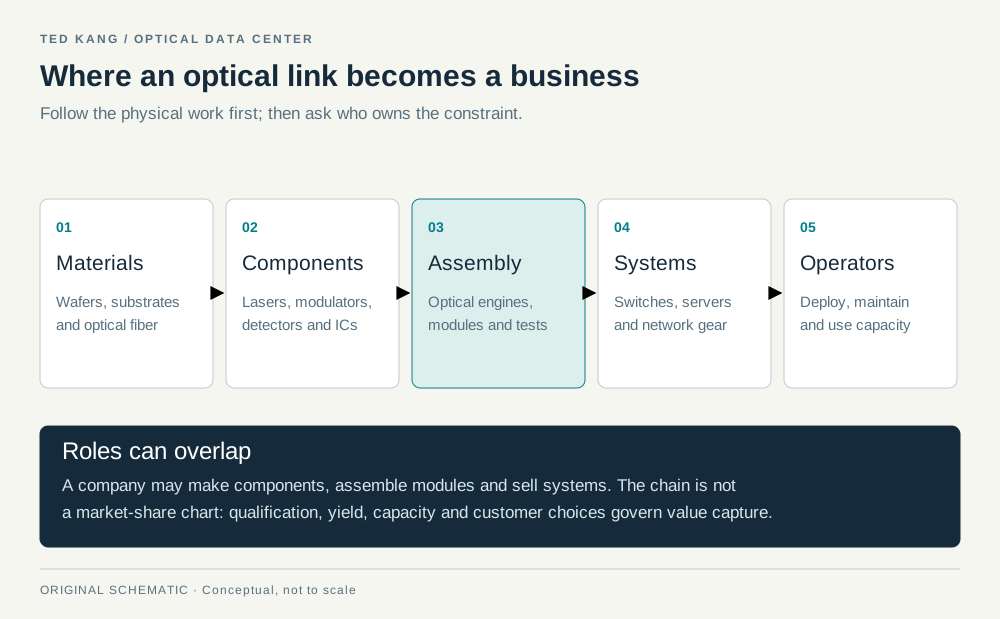
The following examples identify participation, not a ranking of market share:
| Role | Example | Evidence and interpretation |
|---|---|---|
| Lasers, optical components, and systems | Lumentum | Its annual filing describes multiple product families, not a pure AI-laser business. |
| Components and optical modules | Coherent | Its OFC demonstrations span several optical approaches; demonstration status must remain attached to the claims. |
| Optical DSPs | Marvell | Signal-processing products occupy a different layer from a complete transceiver or switch. |
| Switch silicon and integrated optics | Broadcom | Chip bandwidth does not directly equal application throughput. |
| Fiber and connectivity | Corning | Cabling, connectors, and physical installation remain part of the system. |
| Manufacturing and assembly | Fabrinet | Manufacturing capability is distinct from ownership of every underlying component design. |
These roles are documented in Lumentum's FY2026 filing, Coherent's OFC demonstrations, Marvell's optical-DSP announcement, Broadcom's switching announcement, Corning's connectivity offering, and Fabrinet's annual filing.
A simple fictional transaction illustrates double counting. A component supplier sells a laser for $10 to a module maker, which sells the finished module for $100. The operator spends $100 on that module, not $110. Both suppliers legitimately report their own sales, but summing the transactions answers a supply-chain turnover question rather than an end-customer spending question. No actual product price is implied.
Architectural change can redistribute value among these layers. Eliminating one processing block can challenge its supplier while increasing the importance of host capability, optical packaging, or test. Moving a light source can change laser requirements without eliminating the laser. Faster aggregate bandwidth may expand demand, but it does not guarantee an equal increase in every supplier's revenue or margin.
17. Lumentum as a dated case study#
Lumentum is useful here because it participates in optical components and larger systems. Its FY2026 filing uses one reportable segment and two product categories, Components and Systems. Systems also includes industrial lasers. Neither category is a clean measure of AI data-center optics. A reader should not relabel the company's total revenue as AI optical revenue. Lumentum FY2026 Form 10-K.
The company's August 11, 2026 release reports the following for the quarter ended June 27, 2026:
| Q4 FY2026 measure | Reported result |
|---|---|
| Revenue | $1,006.3 million |
| Components revenue | $649.4 million |
| Systems revenue | $356.9 million |
| GAAP gross margin / operating margin | 47.4% / 27.8% |
| Non-GAAP gross margin / operating margin | 50.4% / 36.6% |
The same release reports a large GAAP net loss that included a $7.8 billion one-time, non-cash debt-extinguishment loss from equitizing convertible notes. Operating margin and net income therefore describe different parts of the accounts. The adjustments separating GAAP and non-GAAP results also matter. Lumentum's Q4 FY2026 results and reconciliations.
The video's earlier $808.4 million quarter was Q3 FY2026. The primary release reports 90.1% year-over-year revenue growth; its 47.9% gross margin and 32.2% operating margin were non-GAAP figures. The subsequent Q4 results now provide a later observation. Mixing those periods or omitting the accounting basis would produce a misleading comparison. Lumentum's Q3 release.
A separate piece of evidence concerns strategic supply. On March 2, 2026, NVIDIA and Lumentum announced a nonexclusive arrangement containing a $2 billion investment, a separate multibillion-dollar purchase commitment, and capacity-access rights. These categories must be kept separate: financing, future purchasing commitments, and recognized sales are not the same amount of current revenue. Lumentum partnership announcement.
Coherent announced its own $2 billion NVIDIA investment and nonexclusive arrangement on the same date. That second agreement prevents the inference that a strategic investment makes Lumentum the exclusive supplier of all NVIDIA optical requirements. Coherent partnership announcement.
These facts establish significant activity and customer interest. They do not independently establish a permanent market-share position, a guaranteed margin, or an attractive stock valuation. The operating thesis and the price paid for a security remain separate questions.
18. Manufacturing capacity is a sequence of milestones#
A semiconductor factory announcement is the beginning of a capacity story, not the end. The facility must support the intended process, install and qualify equipment, establish yield, package and test the devices, and satisfy customer requirements. The slowest relevant stage can constrain usable output.
Lumentum's March 26, 2026 Greensboro announcement described a facility intended for six-inch indium-phosphide wafers and an expected production ramp in mid-2028. That timing is a company expectation. An existing building requiring retrofit is not the same as qualified output available to a customer in 2026. Lumentum's manufacturing announcement.
Wafer-size comparisons deserve the same care. A six-inch circle has four times the area of a three-inch circle, because area scales with the square of diameter. Compared with a four-inch circle, it has 2.25 times the area. Those are geometric ratios. Neither number is automatically the increase in good, packaged, qualified devices per unit of cost.
To see why, imagine an intentionally simplified process with 1,000 candidate die locations and an 80% yield. It produces 800 good dies before downstream losses. A larger process with 4,000 locations but a 60% yield produces 2,400, or three times as many. If yield reaches 90%, it produces 3,600, or 4.5 times the earlier output. The invented figures show why area and yield must be analyzed together; they are not estimates for Lumentum or Coherent.
Manufacturing economics also depend on equipment throughput, wafer cost, process steps, packaging, testing, and product mix. A higher-performance device can require a more demanding qualification process. A supplier can report strong demand while still facing a difficult transition from experimental devices to repeatable output.
Product announcements need milestone labels too. Lumentum's March 2026 OFC release called its four-lane, 400G-per-lane 1.6T DR4 demonstration a prototype. That description should remain attached to that specific configuration. It does not imply that every 1.6T product in the market is a prototype, or that this particular prototype is already in volume production. Lumentum's OFC announcement.
19. Judge durability with several kinds of evidence#
An optical supplier can benefit from rising deployed bandwidth, a richer product mix, scarce qualified capacity, and better manufacturing execution. Those drivers can coexist. A strong quarter does not reveal how much each contributed, so the explanation should remain a hypothesis until the evidence separates them.
The same is true in reverse. A declining margin could reflect pricing pressure, a new product ramp, customer mix, underused capacity, or a temporary manufacturing problem. There is no universal gross-margin threshold that proves a durable advantage above it and disproves one below it. A serious assessment follows the operating mechanism rather than assigning the entire story to one percentage.
I would organize the evidence around six questions:
- What is actually shipping? Distinguish a demonstration, customer sampling, qualification, production shipments, and deployment at meaningful scale.
- Which products are growing? Separate laser components, optical engines, modules, circuit switches, telecom products, and industrial products where disclosure permits.
- Where is capacity constrained? A wafer process, packaging line, test operation, or customer qualification can be the limiting stage.
- What changes when supply expands? Compare pricing, mix, yield, utilization, and demand rather than assuming a single outcome.
- How concentrated is the exposure? A strong customer commitment can support planning while leaving concentration and timing risks.
- How does architecture change the content per system? More bandwidth can coexist with fewer components of one kind and more of another.
This framework also improves how we read headlines. “Twice the bandwidth” needs a direction and a boundary. “Lower power” needs an operating point and a comparison. “More capacity” needs a milestone and date. “Strategic investment” needs its financing and commercial terms. “Silicon photonics” needs an explanation of the light source and the functions integrated on the chip.
For the data-center operator, the test remains useful delivered work under real constraints. For the component supplier, the test is converting technical capability into qualified output and sustainable economics. Optics can improve the first outcome without guaranteeing the second for every participant.
20. A glossary for reading the next announcement#
| Term | Plain-language meaning |
|---|---|
| ASIC | A chip designed for a particular function; a switch ASIC performs networking tasks. |
| Bandwidth | The amount of data a connection can carry per unit of time, with direction and accounting boundary specified. |
| Baud | Symbols per second, which is different from bits per second. |
| Bisection bandwidth | The least capacity across a cut dividing a network into two equal-sized groups of endpoints. |
| Breakout | Dividing a higher-rate interface into compatible lower-rate connections. |
| CPO | Co-packaged optics: optical engines integrated close to a main chip within a package assembly. |
| CW laser | A continuous-wave light source whose light can be modulated elsewhere. |
| dB | A logarithmic ratio used for quantities such as gain and loss. |
| dBm | An optical or electrical power level referenced to one milliwatt. |
| DSP | A digital signal processor; in optics it can help condition or recover a signal. |
| EML | A laser and electro-absorption modulator integrated into one device. |
| External laser source | A light source located separately from the optical engine it supplies. |
| FEC | Forward error correction: structured redundancy used to repair a limited amount of corruption. |
| Fiber pair | Two fibers; many duplex arrangements use one for each direction, but exact designs vary. |
| Goodput | Useful application data delivered per unit of time after the relevant overhead and inefficiencies. |
| InP | Indium phosphide, a semiconductor material used in important optical devices. |
| Lane | One constituent signal channel; electrical lanes, optical lanes, wavelengths, and fiber strands need not map one-to-one. |
| Latency | Delay, which can include travel, processing, serialization, and waiting. |
| Leaf | A switch layer that commonly attaches endpoints in a leaf-and-spine network. |
| Link budget | An accounting of allowed and expected losses or impairments under specified link conditions. |
| LPO | Linear pluggable optics, with greater dependence on host-side signal processing and channel quality. |
| LRO / RTLR | An arrangement with retimed transmission and a linear receive path. |
| MEMS | Microelectromechanical systems; tiny movable mirrors are one way to build an optical circuit switch. |
| Modulator | A device that changes light according to the information being transmitted. |
| MSA | A multi-source agreement defining compatibility among participating implementations. |
| Multimode fiber | Fiber supporting multiple spatial propagation modes within its operating conditions. |
| OCS | An optical circuit switch that establishes a light path between ports. |
| Optical engine | A group of optical and related electrical functions that converts or handles signals. |
| Optical I/O | Optical communication brought to the input/output boundary of a compute package or chiplet design. |
| Oversubscription | More potential endpoint-facing bandwidth than upstream capacity at a stated boundary. |
| PAM4 | Four signal levels representing two bits per symbol. |
| Photodiode | A component that converts received light into electrical current. |
| PIC | Photonic integrated circuit: multiple optical functions integrated on a chip. |
| Radix | The number of ports or connections available from a switching element at the stated rate. |
| Retimer | Electronics that recover and retransmit a signal with renewed timing. |
| SerDes | Serializer/deserializer circuitry connecting parallel data processing with high-speed serial signaling. |
| Silicon photonics | Silicon-based integration of optical functions, often combined with other materials for the light source. |
| Single-mode fiber | Fiber designed for one spatial mode; it can still carry multiple wavelength channels. |
| Spine | A switch layer interconnecting leaves in a leaf-and-spine network. |
| TIA | Transimpedance amplifier: circuitry converting a small input current into voltage. |
| Transceiver | Equipment combining transmitting and receiving functions. |
| WDM | Wavelength-division multiplexing: several wavelength channels carried on a shared optical path. |
The technical sources are linked beside the relevant explanations. Product specifications describe their named interfaces and conditions; issuer announcements establish what the issuer reported, not independent fleet benchmarks. All seven figures are original conceptual illustrations. The two interactive examples explain a sequence and a bounded calculation. Neither is a physical link simulator, a product qualification tool, or a model of a named operator's network.
For a broader view of the surrounding equipment, this primer connects to Inside the Data Center. The optical layer is one part of that larger system: it helps turn local computation into coordinated work across distance.
Continue reading. For the concise business framework, read AI Networking: Where Optics Earns Its Place. For the wider physical system, read Inside the Data Center.